

Radio Antennas
There are two basic types of antenna you may find commonly being used in conjunction with Two-way UHF PRS Radio Equipment. The two designs we are focusing on are the "Vertical Whip" and "Yagi Antenna". Each design has it's unique benefits and drawbacks but there is a place for each configuration and knowing the useful attributes of each design may be useful to get the most out of your equipment in different locations.
Vertical whip antennas are widely used for multi-directional radio communication where the direction the signal is intended to travel or being received from is not known, changes often or intended for a wide audience located in multiple directions around the transmitting stations location.
A whip antenna is an antenna consisting of a single straight flexible wire or rod. The bottom end of the whip is connected to the radio receiver or transmitter. They are designed to be flexible so that they do not easily break, and the name is derived from their whip-like motion when disturbed.
The whip antenna can be considered half of a dipole antenna, and like a vertical dipole has anomnidirectional radiation pattern, radiating equal radio power in all azimuthal directions (perpendicular to the antenna's axis), with the radiated power falling off with elevation angle to zero on the antenna's axis.
A "Yagi" or "Beam" antenna is an antenna which radiates or receives greater power in specific directions allowing for increased performance and reduced interference from unwanted sources. Directional antennas provide increased performance over Vertical Whip Antennas (or omnidirectional antennas in general) when a greater concentration of radiation in a certain direction is desired.
All practical antennas are at least somewhat directional, although usually only the direction in the plane parallel to the earth is considered, and practical antennas can easily be omnidirectional in one plane. The most common types are the Yagi antenna, the log-periodic antenna, and the corner reflector, which are frequently combined and commercially sold as residential TV antennas.


"Yagi Antenna"
"Vertical Whip"
A high-gain antenna with a focused, narrow radio-wave beam width a narrow beam width allows more precise targeting of the radio signals. These antennas are most successful in flat, open areas where no mountains lie to disrupt radio-waves. By contrast, a Vertical Whip Antenna is an omnidirectional antenna with a broad radio-wave beam width. This very wide beam allows for a more reliable signal that is best used in mountainous regions, where the signal will propagate reasonably well regardless of terrain. The mountains become the equivalent of rocks in a stream, surrounded by the flowing waves. Low gain antennas are often used in spacecraft as a backup to thehigh-gain antenna, which transmits a much narrower beam and is therefore susceptible to loss of signal.
When transmitting, a "high-gain" antenna allows more of the transmitted power to be sent in the direction of the receiver, increasing the received signal strength. When receiving, a "high gain" antenna captures more of the signal, again increasing signal strength. Due toreciprocity, these two effects are equal - an antenna that makes a transmitted signal 100 times stronger (compared to an isotropic radiator), will also capture 100 times as much energy as the isotropic antenna when used as a receiving antenna. As a consequence of their directivity, directional antennas also send less (and receive less) signal from directions other than the main beam. This property may be used to reduce interference
Wellington Radio Shops.

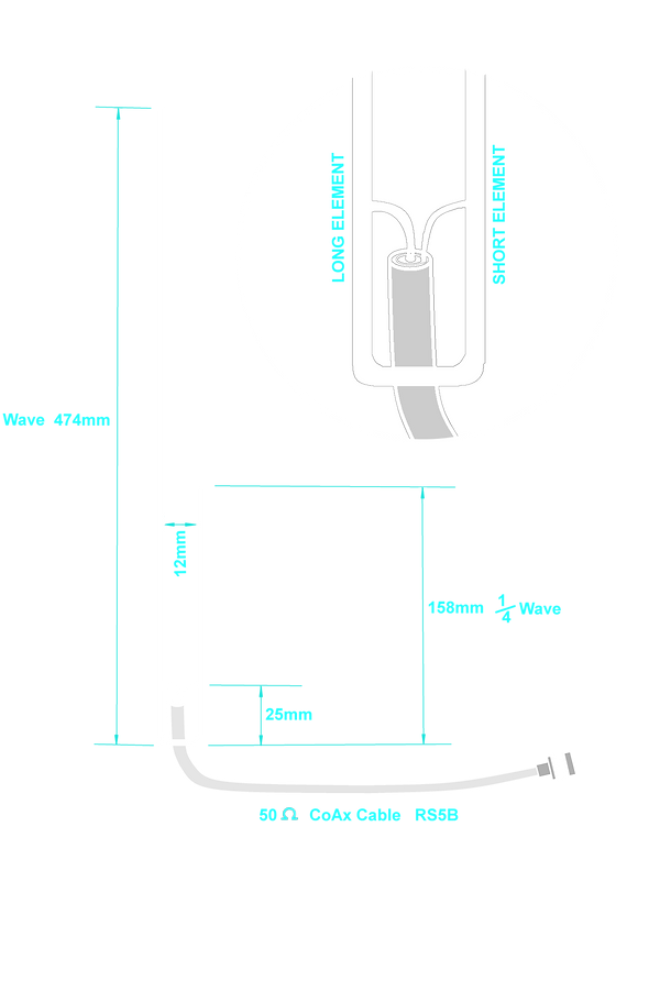
DIY J-Pole Antenna
J-Pole Antenna
The J-pole antenna, also called the Zepp' antenna (short for Zeppelin), was first invented by the Germans for use in their lighter-than-air balloons. Trailed behind the airship, it consisted of a single element, one half wavelength long radiator with a quarter wave parallel feedline tuning stub. This was modified into the J-pole configuration by at least 1936 with continuing refinements by 1943 and became popular with amateur radio operators because it is effective and relatively simple to build.
Characteristics
The J-pole antenna is an end-fed omnidirectional half-wave antenna that is matched to the feedline by a quarter wavetransmission line stub. Matching to the feed-line is achieved by sliding the connection of the feedline back and forth along the stub until a VSWR as close as possible to 1:1 is obtained. Because this is a half-wave antenna, it provides a small gain over a quarter-wave ground-plane antenna.
Like all antennas, the J-pole is sensitive to surrounding electrically conductive objects and should maintain
sufficient separation to minimize near field interactions.
The J-Pole is very sensitive to conductive support structures and will achieve best performance with no electrical bonding between antenna conductors and the mounting structure.
Feed and mounting
The J-pole antenna and its variations should ideally be fed with balanced line, however a coax feed line may be used if it includes a means to suppress feed-line RF currents. A choke balun is often used, with about five turns of coax, or an air transformer. Typical construction materials include copper pipe, ladder line, or twin-lead. The feed-point of the J-pole is somewhere between the closed low-impedance bottom and open high-impedance top of the J stub. Between these two extremes a match to any impedance between the low to high impedance points is available.